Robot build phase 2: Set up the SLAMTEC Aurora S
The second phase of the robot build focuses on setting up the SLAMTEC Aurora S spatial perception system with the D-Robotics RDK S100P. The tasks include connecting the Aurora S to the RDK, setting up the AuroraCore Remote Visualizer app, and viewing spatial data using the app.
SLAMTEC’s Remote Visualizer app is a diagnostic tool for viewing perception data in a GUI as it is sent to the connected system. The app is available on Windows, Mac, and Linux, but running it on the RDK ensures the Aurora S communicates with the RDK successfully before attempting to set up the SLAMTEC Aurora SDKs for app development.
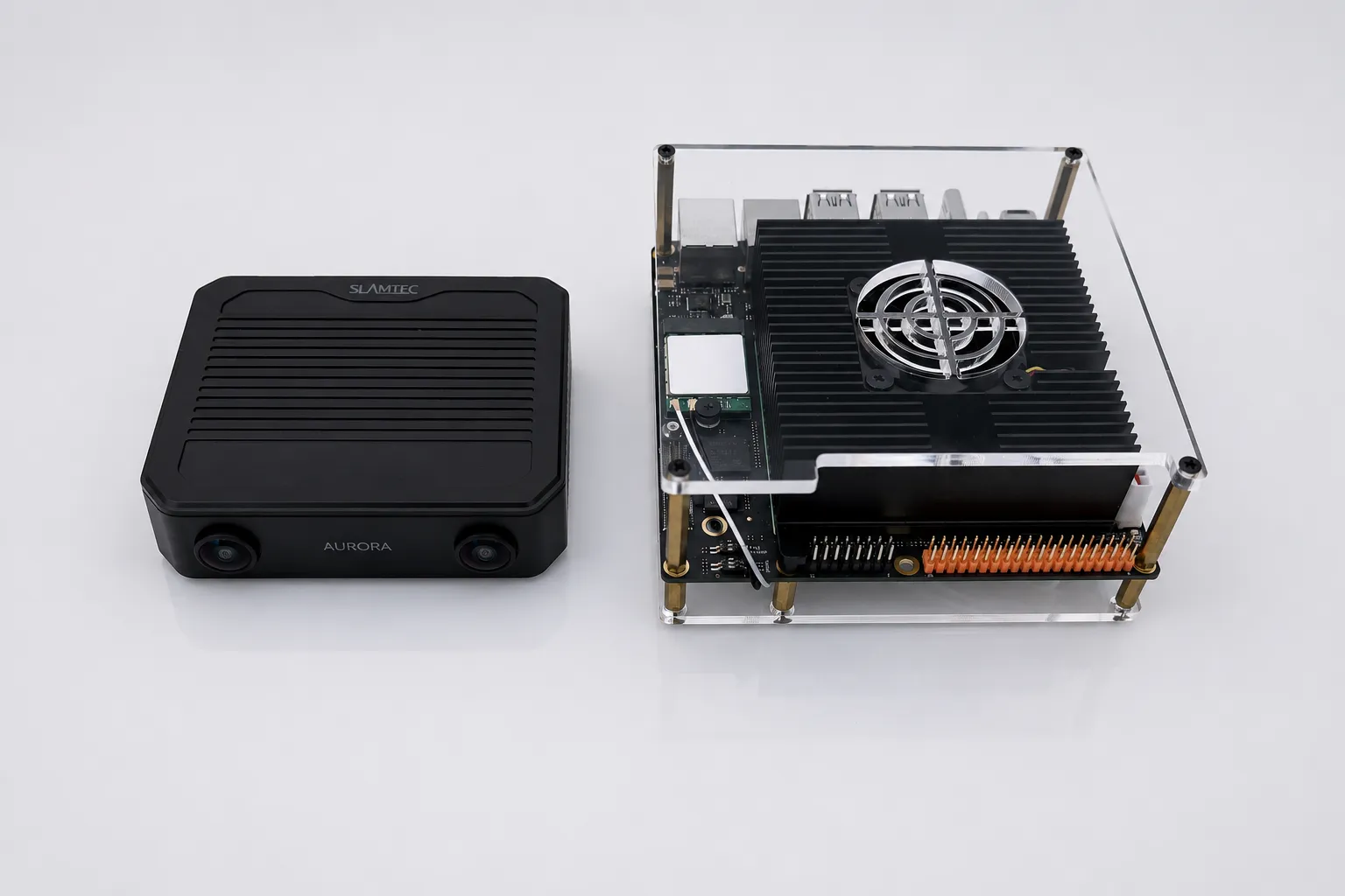
For the robot build, consolidating components and offloading computing operations from the RDK saves resources and physical space on the RDK and in the future robot chassis. The Aurora S provides these benefits in a palm-sized device by integrating multiple sensory components and its own engine for processing the spatial perception data.
Aurora S overview §
The Aurora S is a powerful device that gives the robot awareness of its surroundings by continuously scanning and mapping the environment. On many robots, multiple components handle these capabilities and the RDK processes the raw data: a setup that consumes substantial resources, power, and physical space. The Aurora S covers these capabilities as a device the size of a smartphone, freeing up resources on the RDK.
The Aurora S provides spatial data that lets the robot perform these tasks in real time:
- Track its own position and orientation.
- Identify surfaces and objects in view, along with their size, position, and orientation.
- Measure distances.
- Build and remember a 3D map of every environment it encounters.
Aurora S components:
- Dual 180° fisheye cameras: Provide a much wider field of view than HD cameras or the central field of human vision.
- Integrated IMU (inertial measurement unit): Combines three sensors to measure motion and orientation:
- Accelerometer: Measures linear acceleration.
- Gyroscope: Measures rotational velocity.
- Magnetometer: Measures the Earth’s magnetic field for an absolute heading.
- Onboard AI processor and neural accelerator: Runs the vSLAM pipeline, so the RDK doesn’t have to.
- Power supply: Powers the device independently, freeing up power and connectors on the robot.
- Ethernet connection: Streams data to connected host devices.
The device streams data to connected hosts over Ethernet at 15 fps. The data includes:
- Stereo camera feed: Synchronized video from the two 180° fisheye cameras, providing the raw visual input.
- 6DOF pose: The device’s position and orientation in 3D space, expressed as six values (x, y, z coordinates plus pitch, roll, yaw rotation).
- Dense 120° depth map: Per-pixel distance measurements across a 120° field of view.
- Pixel-level semantic segmentation: Labels every pixel in each camera image to identify the object type (floor, wall, chair, person, and so on).
- 3D point cloud: The device’s live spatial map, expressed as a constantly updating set of 3D points representing surfaces it has seen.
At a glance §
| Item | Value |
|---|---|
| Aurora S default IP | 192.168.11.1 |
| S100P interface used | eth0 (192.168.11.x subnet) |
| Power input | DC 9-24V via XT30PW-M, or USB-C PD 3.0 (~10W) |
| Visualizer build | AuroraCore Remote Visualizer, Linux aarch64 AppImage |
| Required runtime dependency | libfuse2/jammy |
| Connection method | Ethernet only (USB-C and USB 3.1 OTG do not present as network interfaces) |
Prerequisites §
- D-Robotics RDK S100P running the D-Robotics Ubuntu 22.04 (jammy) image.
- SSH access to the RDK S100P. See the Remote Access guide for more information.
- SLAMTEC Aurora S, supplied power adapter, and an Ethernet cable.
- Download the AuroraCore Remote Visualizer app for Linux aarch64.
Power requirements §
The Aurora S turns on and boots automatically when supplied with power. The device takes about 30 seconds to boot.
There are two options for powering the device: an XT30PW-M plug that connects to the supplied power adapter, and a PD 3.0 USB-C port that is only for power input. The RDK S100P USB ports don’t supply enough power for the Aurora S, so an external source must power the Aurora S. The Aurora S also has a USB 3.1 port that isn’t for power input, it’s for hosting other devices, such as a Wi-Fi adapter.
Configure Ethernet §
The RDK S100P communicates with the Aurora S through Ethernet. When using the default Ethernet settings on the D-Robotics RDK S100P, the eth0 Ethernet port is the general-purpose port for communicating with the Aurora S. When facing the ports, eth0 is the left Ethernet port, which uses the U43 ID in D-Robotics documentation. The eth1 interface will not connect to the Aurora S when using the default RDK Ethernet settings.
| Interface | Subnet | Purpose |
|---|---|---|
Left port: eth0 | 192.168.11.x | Aurora S |
Right port: eth1 | 192.168.127.x | Not used for Aurora S |
Complete these steps to connect the Aurora S to the RDK S100P:
- Power off the Aurora S.
- Connect the Aurora S to the
eth0interface using an Ethernet cable. - Power on the RDK S100P.
- After the RDK S100P boots, power on the Aurora S and wait for a green indicator on the Aurora S. The S100P connects to the
192.168.11.xaddress automatically through DHCP from the Aurora S. - Verify the connection to the Aurora S by pinging it:
Replies confirm the Aurora S is communicating with the S100P successfully. If there is no reply, power cycle the Aurora S, then try again.
Terminal window ping 192.168.11.1
Install Aurora Remote Visualizer §
The AuroraCore Remote Visualizer app displays perception data from the Aurora S in a GUI, so you can preview the data before setting up the Aurora SDK for app development. SLAMTEC provides the AuroraCore Remote Visualizer app for Windows, Mac, and Linux. The RDK S100P requires the Linux aarch64 version of the app.
Install libfuse2 §
The Aurora Remote Visualizer app is distributed as an AppImage, so it requires the libfuse2 Linux package. The D-Robotics Ubuntu image doesn’t include libfuse2 by default, and the version available in the default package sources isn’t installable without pinning. Install the Jammy-pinned version explicitly.
sudo apt install libfuse2/jammyInstall the AppImage §
SLAMTEC distributes the visualizer as an AppImage inside a tarball. To install the app on the RDK S100P, complete these steps after installing libfuse2:
- Download the AuroraCore Remote aarch64 build from the Tools > Linux section of the SLAMTEC support page.
- On the RDK S100P, unpack the archive. The archive name contains a space, so quote it or use tab completion:
Terminal window cd $HOME/Downloadstar -xzf "AuroraCore Remote_aarch64.tar.gz" - Move the AppImage into a dedicated directory and make it executable:
Terminal window mkdir -p $HOME/AppImages/AuroraCoreRemotemv "AuroraCore Remote_aarch64/AuroraCoreRemote.AppImage" $HOME/AppImages/AuroraCoreRemote/chmod +x $HOME/AppImages/AuroraCoreRemote/AuroraCoreRemote.AppImage - To avoid typing the full path to the Remote Visualizer app each time, add an alias to
~/.bashrc:Now you can launch the app withTerminal window echo "alias aurora='$HOME/AppImages/AuroraCoreRemote/AuroraCoreRemote.AppImage'" >> ~/.bashrcsource ~/.bashrcaurorain your terminal.
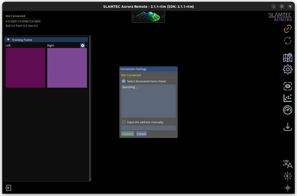
Connect to Remote Visualizer §
Launch the visualizer:
auroraIn the Connection Settings dialog, enter 192.168.11.1 in the Manually enter address field and click Connect.
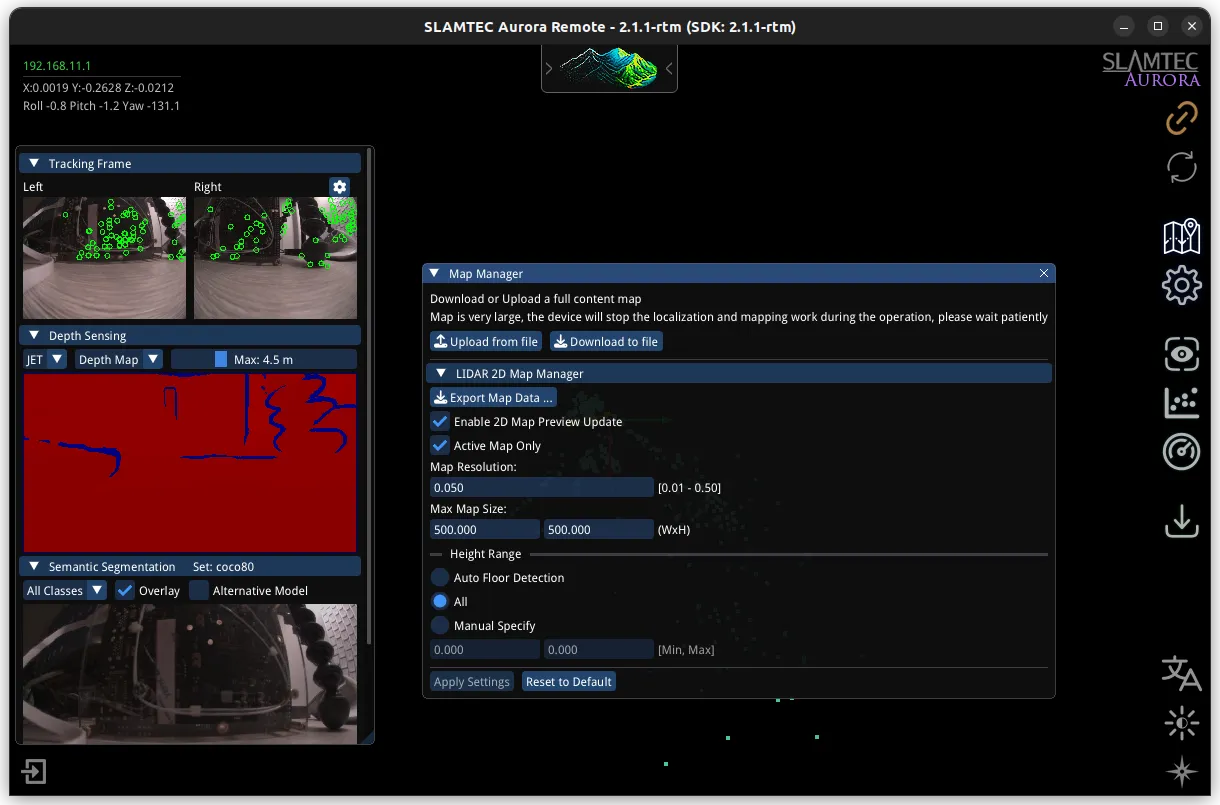
Remote Visualizer data §
Remote Visualizer displays this data:
| View | Description |
|---|---|
| 3D map view | The 3D map as it builds in real time, with a small marker showing where the Aurora is and which way it’s facing. |
| Camera feed | Video from the dual fisheye cameras. |
| Stereo depth map | Images that color-code each pixel to display surface depth. |
| Semantic segmentation overlay | Recognized objects highlighted by their class color. |
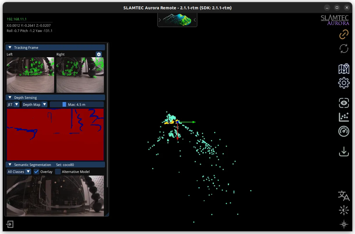
3D map view §
The 3D map view is the main panel of the visualizer, showing the Aurora’s environment and its position within it. Three layers are drawn together in the same 3D space: the device’s current pose, its movement history, and the accumulated map of the surfaces it has observed.
The 3D map view displays this data:
- Colored arrows: The device pose.
- Red arrow: X axis, typically forward or right.
- Green arrow: Y axis.
- Blue arrow: Z axis, typically up.
- Yellow points and connected lines: The device’s movement history saved as keyframes.
- Other points: The accumulated 3D map of the environment.
The colored arrows are the spatial axes that indicate the 6DOF pose of the device. The pose is the device’s position and orientation in the 3D map. The origin point where all the arrows meet is the position, and the direction each arrow points is the orientation.
The small grey and teal cluster at the map origin is the 3D model of the Aurora S, rendered at the current pose so you can see the device’s position and orientation in the context of the map.
The yellow points and the lines connected to them are keyframes (anchor points) from the SLAM system’s trajectory. Each yellow point is a past camera pose the SLAM engine saved as a keyframe, and the lines connect them to show the path the Aurora S has traveled through 3D space.
Camera feed §
The camera feeds display raw video from the device’s two 180° fisheye cameras, shown side by side. Each frame looks distorted around the edges because a 180° view can’t be mapped onto a flat image without warping, the same reason world maps stretch the polar regions. The tradeoff buys roughly three times the field of view of a typical 60° camera lens, which gives the SLAM engine far more visual features to track per frame.
Stereo depth map §
The stereo depth map is a flat image of what the cameras see, with each pixel colored by the distance to that surface. The visualizer’s default JET colormap progresses from red to yellow, green, and then blue as distance increases, so you can read the room’s geometry at a glance. The Aurora S computes the depth map in real time from the two camera feeds using a deep-learning model, which maintains accuracy in conditions where traditional stereo matching fails: low-texture walls, strong glare, or uniform surfaces.
Semantic segmentation overlay §
The semantic segmentation overlay displays the current camera frame with every recognized object tinted to identify its type. The Aurora S runs an on-device AI model that classifies each pixel into an object class (person, chair, floor, wall) drawn from a library of 80 indoor and 18 outdoor categories; pixels the model can’t confidently identify aren’t tinted. The result is a live visualization of what the device understands about the scene.